Open Channel Flow LAB REPORT

Aim

TO study the open channel flow in a rectangular channel

Objectives

1. Investigate the uniform flow condition in open channel flow

2. Verify the manning’s equation

Theory on Open Channel Flow 

According to Dr. Khalil M. ALASTAL (n.d) an open channel is like a duck with flowing fluid and whose surface is exposed to atmosphere.

As the atmospheric pressure remains constant through the length of duct so the fluid flows only due to the difference in potential energy.

According to Ivan Gramatikov (n.d) flow rate of water in a channel is the product of its area with the velocity of water through that area 

Q=A×V

Where A is area of cross section and V is velocity of the fluid.

Volumetric flow rate is the ratio of volume of flowing fluid to the time taken Q=∆V/t. 

Area of the rectangular channel is the product of its width with the depth of the water flowing through that area A=b ×y_o. 

Where b is the width of the rectangular channel and y_o is the depth of the flow.

According to David Knighton Wetted perimeter is the perimeter used for the wet cross section area. 

In an open channel flow it can be define as the sum of the sides of channels those are in direct contact with the flowing fluid. 

With the increase in wetted perimeter the friction losses increase resulting in the decrease in heat.

P=b+yo+yo
P=b+2 ×yo  

According to Bernard Le Méhauté channel flow efficiency of an open channel flow in measured in the term of hydraulic radius some time also called hydraulic mean depth. 

It is ratio of the channel cross section area to the wetted perimeter. Hydraulic radius is the function of shape of the channel not the half of the hydraulic diameter. 


R=A/P

According to Manning R. (1891) manning equation is used to find the theoretical flow rate of the fluid flowing under the action of gravity also called the open channel. 

Q=  A/n  × R^(2/3)  × So^(1/2)

Here So is the slope of the bed of the channel which enable the water to flow under the action of gravity. 

Read about Flow of a Compressible Fluid and Laminar and Turbulent fluid flow in Pipe

Procedure of Open Channel Flow 

Following is the procedure to perform the experiment according to Dr. Khalil M. ALASTAL (n.d)

1. Set up the flow channel apparatus

2. Adjust the support frame feet so that the flow channel does not rock

3. Reset the clock dial to zero 

4. Check the water depth along the length of channel, it should be constant to prove that the initial slope of bed is zero

5. With the help of a jack at the back of channel, set the slope of the channel to a gradient of 1/500 that is 0.002

6. Start the pump and introduce water into the channel by operating valves

7. Use the flow control valve to set the flow rate of water at 2.5 liter/sec 

8. Allow the flow in the channel to settle and then take the measurement of depth of water with the help of scales placed at their respective position

9. Note that the space between the scales should not be greater than 2 mm

10. Now adjust the flow control valve three times to set the flow rate to three different values of 2.0, 1.5 and 1.0 liter/sec and note the depth of water for all three flow rates.

11. Repeat the complete above procedure for the slope of gradient 0.005 and note the values in the below given tables

12. Calculate the value for Area, Wetted perimeter, Hydraulic Radius and Theoretical Flow rate.

13. Also convert the measured flow rate from liter per second to cubic meter per second

Observations Open Channel Flow 

Numbers of experiments were performed according to above mention procedure, with different flow rates and with different slopes and data was recorded in the following table.

Analysis on Open Channel Flow 

Using the data gathered as the result of experiment performed, to get the values of mean depth, Area, wetted perimeter, hydraulic radius and theoretical flow rate with the help of formulas mention above.  

Conclusion on Open Channel Flow 

Values for the measure flow rate were recorded using flow meter and value of theoretical flow rate was calculated by using manning equation. 

Difference between the values of these two flow rates is because the theoretical flow rate depends on the slope of the channel bed and also on the other factory like manning roughness coefficient but the measure flow rate depends only on the area and velocity of the fluid through that area.

Applying the same flow rate at different slopes has shown that the change in the slope of bed change the theoretical flow rate value as it depends on the depth of the flow. 

Value of theoretical flow rate at 0.002 gradient is less than the value at the 0.005 gradient, this show that increasing the gradient increase the theoretical flow rate while the measured flow rate remain the same.

VENTURI METER AND ORIFICE PLATE LAB REPORT

Venturi meter effect and orifice plate effects are two main and very important phenomena in the fluid mechanics sub-field of mechanical engineering. 

In this post, the effect of the venturi meter and orifice plate on the fluid flow will be discussed and complete work will be presented in the form of a report. 

Aim
This experiment aims to study the overall meter coefficient C of the Venture meter and Orifice plate

Objective
The objectives of this experiment are
1. Understand the effect of a decrease in the area on the velocity and pressure of the flowing fluid
2. Understand the relationship between velocity and pressure of flowing fluid
3. Find the meter coefficient for the venture meter and orifice plate

Venture Meter

According to Michael Reader-Harris (n.d), a Venture meter is an instrument used to study the flow of fluid when it passes through the converging section. 

There is an increase in the velocity and decrease in the pressure of the flowing fluid when the area available to flowing fluid decreases, this effect is called the venture effect named after the physicist who first introduces this theory. 


Orifice Plate

According to Michael Reader-Harris (n.d), an Orifice plate is an instrument used for three different applications one to measure the flow rate, second to restrict the flow, ad third to reduce the pressure of the flowing fluid. 

It depends on the orifice plate-associated calculation method that either the mass flow rate or the volumetric flow rate is used for calculation. 

It uses the Bernoulli experiment which shows the relationship between velocity and pressure for a flow of fluid. When one increases then the second one decrease.


According to DANIEL MEASUREMENT and control white papers, the following are the different types of orifice plates
  • The Thin Plate, Concentric Orifice
  • Eccentric Orifice Plates
  • Segmental Orifice Plates
  • Quadrant Edge Plate
  • Conic Edge Plate

Theory of Venturi Meter and Orifice Plate

According to Miller, R.W (1996) principle of continuity state that the decrease in the area of the flowing fluid will increase the velocity of the flowing fluid. 

With this increase in the velocity of the fluid, the fluid pressure will decrease to conserve mechanical energy according to the law of conservation of energy. 

Flow rate is the product of the velocity of the flowing fluid with the area from which the fluid is flowing. In the venture meter, the area of the tube decreases gradually due to which the velocity increase to keep the flow rate constant. 

In the orifice plate, there is a sudden decrease in the area of the flow due to the restriction of the orifice plate. Due to this velocity will increase and pressure will decrease.

According to Bernoulli’s equation

P1+  1/2×ρ×v1^2+ ρgh1=P2+  1/2×ρ×v2^2+ A
A the change in height is zero so

P1+  1/2×ρ×v1^2= P2+  1/2×ρ×v2^2

P2 - P1=  1/2×ρ×〖(v〗1^2- v2^2)

As we know

Q=AV

Q=A √((2(P2-P1)/ρ)/(〖[A1/A2]〗^2-1))

As we know

P= ρgh

So

Q= A1 √((2×g × ∆h)/(〖[A1/A2]〗^2-1))

In above equation 

Q is the flow rate

A1 is the area before the convergence

A2 area of convergence (throat)

∆h is a difference in height of heads across the convergence

For real fluid, there will be differences in the theoretical and measured values this may be due to the meter coefficient C

Q= C ×A1 √((2×g × ∆h)/(〖[A1/A2]〗^2-1))

Apparatus
Orifice Tube and Venture Meter
Supply Hoses
Measuring Tank

Procedure Venturi Meter and Orifice Plate

To set up the orifice tube and venture meter apparatus two tubes were connected one on each of the outlet and inlet of the apparatus. 

The tube which was connected to the venture meter outlet was further connected to the measuring tank. 

To level the orifice meter and venture tube apparatus, adjustable screws are provided at the apparatus.

The apparatus was connected to the power source to run the motor for the water supply. The bench valve and the control valve of the apparatus were open to let the water move into the tube and to remove all the air pockets.

To raise the water level in the manometer tubes the control valve was closed gradually and when the height of the water level was enough high then the bench valve was gradually closed. 

With both valves closed there was static water in the meter at a moderate pressure

The flow rate of the water was recorded and the height of the water level was also recorded in all the tubes

The difference between the heights of the water level and the flow rate will change upon opening any one of the apparatus valves. 

The flow rate was calculated by noticing the time required to fill the tank of a known weight and at the same time the level of the water in the manometer tubes was also recorded

The same process is repeated for different flow rates

Sample Calculations for Venturi Meter and Orifice Plate


Mass = 6 Kg

Volume = 6/1000 = 0.006 cubic meter

Time = 12.81 sec

Flow Rate = 0.006/12.81 = 0.0004684 cubic meter/sec

For Venturi Meter
  
 C=  Q/A_1 ×1/√((2×g × ∆h)/(〖[A_1/A2]〗^2-1))

C = (0.0004684/0.053066)×  1/√((2×g × 0.267)/([26/16]^4-1))

C = 0.00943

Experimental Results Venturi Meter and Orifice Plate


Discussion Venturi Meter and Orifice Plate

1. Curve shown in the graphs shows the linear relationship between flow rate and difference in height

2. Result shows that with a decrease in the flow rate, the value of the ∆h also decreases. So it can be said from the results that the difference in the height of the water level is directly proportional to the flow rate.

3. Change in the height of the water column of the venture meter is much less than the change in the height of the water column in the orifice plate this is because the difference in diameter of the areas of the orifice is much more than the venture meter. 

So we can say that the difference in height of the water column is directly proportional to the difference in the diameter of the area.

Conclusion Venturi Meter and Orifice Plate

An experiment was conducted to find the overall meter coefficient C in the venture meter and orifice tube and results show that the flow rate and ∆h are directly proportional to each other and along with this ∆h and the ∆d are also directly proportional to each other. Both these things are important as they are used to calculate the overall meter coefficient C

References

1. Michael Reader-Harris (n.d) Chapter 2 Orifice plate, Orifice Plates and Venture Tubes, Spring
2. Miller, R.W (1996) Flow Measurement Engineering Handbook 3Rd ED. McGraw-Hill Book, New York N.Y
3. USBR (1996) Flow Measurement Manual. Water Resource Publication LLC Highland Ranch Co 
4. Michael Reader-Harris (n.d) Chapter 3 Venture tube, Orifice Plates, and Venture Tubes, Spring

Design and Development of Automated circle drawer


Aim of this mechanical engineering project is to design and develop an automatic circle drawer which can be used to draw circles of different diameter. This task is a perfect mechanical engineering semester project which can enables students to learn about design an development of product. 
Main topics which will be covered int this mechanical project are as follow

  • Concept Designing
  • Concept Design Selection
  • CAD modeling
  • Design detail description
  • Manufacturing considerations 

Analysis of three different material for flywheel


Current selection of material and manufacturing process for the flywheel has been clearly described and critically evaluated in Project 2 - Analysis of current material and manufacturing process of flywheel but there are other materials and manufacturing process that can be used instead of current material and manufacturing process to increase the performance, reliability and cost effectiveness of flywheel. Three of these materials and their manufacturing process are discussed below.

Analysis of current material and manufacturing process of flywheel


Flywheel is a mechanical device used to store the rotational kinetic energy. The main application of the flywheel is to provide the kinetic energy whenever the load torque is greater the drive torque. Amount of energy store in a flywheel depends on three things geometry of flywheel, angular velocity of flywheel and density of material used. Whereas the flywheel ability to handle the stresses and range of angular velocity at which it can rotate safely, depends on the material of the flywheel. Therefore the material selection is one of most important aspect of flywheel manufacturing.  

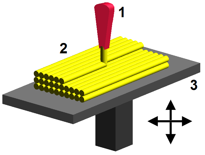
Fused Deposition Modeling - 3D Printing


FDM by Zureks


Fused deposition modeling is an additive layer manufacturing process also known as layer by layer manufacturing process because in this process a 3 dimensional object is made by adding very thin 2 dimensional layers. Process starts with generating the computer aided design (CAD model) of the component which needed to be manufactured. Then second step is to convert the computer aided design file in to STL (standard triangulation language) file, this file format is internationally accepted by all additive layer manufacturing machines. Third step is to slice the 3 dimensional STL file into 2 D cross sections, this is done by the additive layer manufacturing machine. In fourth step the physical development of the desire component is done. After complete manufacturing of the component the post processing is required which is fifth step where finishing process like cleaning and curing is done and final the component is read to be used.