Fused deposition modeling is an additive layer manufacturing process also known as layer by layer manufacturing process because in this process a 3 dimensional object is made by adding very thin 2 dimensional layers. Process starts with generating the computer aided design (CAD model) of the component which needed to be manufactured. Then second step is to convert the computer aided design file in to STL (standard triangulation language) file, this file format is internationally accepted by all additive layer manufacturing machines. Third step is to slice the 3 dimensional STL file into 2 D cross sections, this is done by the additive layer manufacturing machine. In fourth step the physical development of the desire component is done. After complete manufacturing of the component the post processing is required which is fifth step where finishing process like cleaning and curing is done and final the component is read to be used.
1.0 Working
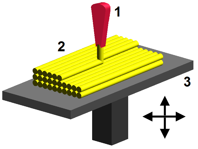
In fused deposition modeling the material which is in form of solid filament, is feed from the roller into the head of the machine where the material is first melted and then extruded out through the preheated nozzle of the machine. Material is extruded on to a table called build plate form whose temperature is maintained below the material melting temperature. As material is feed through the controllable nozzle which move only in the horizontal direction and deposit the molten material on the building plate form to make a thin layer two dimensional profile.
After one layer is deposited the building plate form is lower down equal to the thickness of the layer to be deposited and after that second two dimensional layer of the material is deposited above the first layer. When second layer solidified it make a weld like connection with the lower layer and like this with more two dimensional layers, a three dimensional component is obtain. In the case of over handing feature in the component design, some support material will be required for processing that overhanging feature. The support material is deposited just before the overhanging feature is required with the help of a second nozzle. After the manufacturing process is completed, the semi-finished product is taken for post processing like cleaning and removing of support material form the main part and after that the component is ready for use.
2.0 Materials
Material used in the fused deposition modeling is supplied in the form of wire with diameter of about 1.5 millimeter and the materials that are used are elastomer, eutectic metals, wax, glass fiber reinforced material, thermoplastics and ceramics. Build material in the form of pellets can also be used instead of the filament form. Material used for the support material is mostly nylon and wax type material. The support materials used are either broken away or it may be water soluble.
3.0 Applications
Fused deposition is mostly used for the development of the conceptual models of the products and for the products like pattern, cores and other tooling used in other manufacturing processes. Fused deposition modal is also used for the production of the medical related models and products. To some extend fused deposition modeling is used for the production of functional prototypes which are used to test the design of a product.
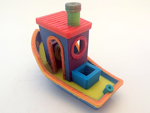
By RepRap.me [GFDL 1.2], via Wikimedia Commons
4.0 Advantages of Fused Deposition Modeling
• Fused deposition modeling have low labor cost
• Fused deposition equipment cost is moderate
• Cost related to finishing in fused deposition modeling is very low
• Fused deposition modeling is environment friendly process as it has very good material utilization
• Fused deposition modeling have the ability to produce the layer thickness in the range of 0.05 to 0.75 mm
• Fused deposition modeling have the ability to produce the minimum sectional thickness of about 0.3 mm
• Building material of different color can be used in fused deposition modeling
• Component made from the fused deposition modeling have almost zero porosity
• Fused deposition modeling process has the ability to provide the tolerance of about 0.1 to 0.25 mm
• The surface roughness of the parts made form fused deposition modeling is in the range of 6 to 12 micro meter Ra
• In fused deposition modeling no post curing process is required which make this process little faster and more economical than some other additive layer manufacturing methods like selective laser sintering
• Fused deposition modeling process support more material than other additive layer manufacturing process like selective laser sintering
• Fused deposition modeling can be used anywhere because its environmental friendly and non-toxic process.
5.0 Disadvantages of Fused Deposition Modeling
• Product building speed of fused deposition modeling is between slow to medium but it truly depends on the size and type of the product. Building speed is very slow for solid parts but medium for hollow parts
• Lead time in fused deposition modeling is between one to two weeks
• Build and support material used in fused deposition modeling are very expansive
• Fused deposition modeling is only economical for very small production quantity
• Product dimensions in fused deposition modeling are limited to 600 mm, 600mm and 500 mm
• In fused deposition modeling finishing processes are required to improve the surface condition of the final product
• Stair stepping case effect is a big problem associated with fused deposition modeling
• Surface finish produce by the fused deposition modeling is not as good as produce by the other additive layer manufacturing process like selective laser sintering and 3 dimensional printing.
• With fused deposition modeling it is very difficult to produce features like thin walled members, sharp edges and acute angle


No comments:
Post a Comment