Vacuum Molding


Expandable mold vacuum molding is one which uses vacuum pressure to mold around the metal plate pattern. This process was invented by the Japanese in 1970.


Steps involves in vacuum molding
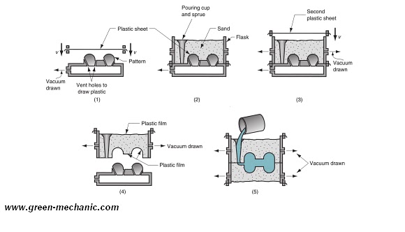
Step 1

Pattern is made from the metal and have specifically design hole in them to withdraw air to create the pressure. A preheated thin plastic sheet is placed over the patter and held tightly with metal plate because of the vacuum.

Step 2

A special design bucket is placed over the pattern and filled with the sand. All other things like spur, runner, riser etc are made. 

Step 3

A plastic sheet is placed over the sand and vacuum is created to held the sand tightly together and so the sand take the shape of the pattern

Step 4 

Vacuum is released and bucket is lifted above the pattern 

Step 5

Other part of the mold is made is the same way and they attached together to get the one complete mold. Then a hot molten metal is poured into the mold to get the required output.


Advantages of vacuum molding

  • No binder is required
  • Sand is recoverable
  • No effects due to moisture because no water is used in this process

Disadvantages of vacuum molding

  • Relatively slow process
  • Process cannot be Mechanization  

Difference Between Izod and Charpy Test


There are two types of test use for testing the Impact resistance of any material one is Izod Impact resistance test and other is Charpy Impact resistance test. Both of them use the same principle to test the Impact resistance of any material but still there are may difference in them and our today's article will show these difference between Izod and Charpy Impact  testing 


Izod vs Charpy


Specimen Position

Position of specimen is both the experiment is different from each. In the Izod method, the test material was placed in a vertical position, while in the Charpy method, the test material was placed horizontally.


Point of Strike 

Point at which the hammer strike the specimen is different for both of them. In Izod test hammer strike at the upper tip of specimen while in Charpy test hammer strike at point of notch but in opposite direction 

Direction of Notch

Face of specimen which faces the striker is different. The notch face in the izod test is facing the striker, fastened in a pendulum, while in the charpy test, the notch face is positioned away from the striker.

Type Of Notch
In hardness testing two types of notches are used V-notch and U-notch. In the Charpy method, there are two kinds of notches, the V-notch and the U-notch, while in the Izod method, there is V-notch is used

Specimen Dimensions

Even if you are testing the same material the test specimens have different dimensions for each test. The basic Izod test specimen is 75 x 10 x 10mm (2.95" x 0.394" x 0.394"); the basic Charpy test specimen is 55 x 10 x 10mm (2.165" x 0.394" x 0.394") 

Hammer Type

Hammer which use as striker is different in both test. Izod use Farming hammer as striker where as Charpy use Ball Pin hammer as striker


Permanent Mold Casting Processes


Permanent Mold Casting Processes are one in which there is a one mold made of metal which could be used again and again many times. Mold material is usually cast iron or steel. Mold is usually consist of two parts, which are attached to each other and metal is poured and when metal cools, mold is opened and part is removed


Basic Permanent Mold Casting Processes

  • Die casting
  • Hot chamber die casting
  • Cold chamber die casting
  • Centrifugal casting
  • True centrifugal casting
  • Semi centrifugal casting
  • Pressure casting
  • Vacuum molding casting
  • Slush casting
  • Ingot manufacturing

Steps involves in Permanent Mold Casting Processes

Step 1

Two parts of the mold are heated and are spared with some material which prevent the molting material from sticking with mold walls.


Step 2

If there is any internal cavity core is place in the mold and mold is closed


Step 3

After the mold is closed molten metal is poured into the mold.

Step 4

When the molten material is cool then then mold is open and part is removed


Applications Permanent Mold Casting Processes


  • Because of the high initial cost of the mold. These types of process are suitable for the mass production
  • Parts casted are piston, pump bodies, car engine parts, air craft parts etc
  • Metals cast: aluminum, magnesium, copper-base alloys, and cast iron

Advantages Permanent Mold Casting Processes


  • High dimensional accuracy 
  • Good surface finish
  • High production rate
  • Low cast of product

Disadvantages Permanent Mold Casting Processes


  • High initial cost
  • Limitation of material (low melting metals only)
  • Only simple geometry


Different Types Of HOLE In Pro E


In Pro/ENGINEER holes are created using the HOLE dialog box. The HOLE dialog box is displayed when you choose Insert > Hole from the menu bar or PART > Feature > Create > Solid > Hole from the Menu Manager.

You can create three types of holes using the HOLE dialog box.
  • The first type is a straight hole,
  • the second is a sketched hole,
  • the third is a standard hole.          


straight hole

Straight holes are the holes that have a circular cross-section having a constant diameter throughout the depth. They start at the placement plane and terminate at the user-defined depth or at the specified end surface.

sketched hole

The Sketched option allows you to sketch the cross-section for the hole that is revolved about a center axis. This option is used to draw custom shapes for the hole. When you choose this radio button in the HOLE dialog box, the system opens a new window with the sketcher environment. The cross-section for the hole is sketched using the normal sketcher options available. While drawing the sketch, a center line must be drawn that acts as the axis of revolution for the section of hole. The sketched holes can be a blind or a through hole depending upon the dimensions of the section sketch.

standard hole

The holes created using the Standard Hole option are based on industry standard fastener tables. The Standard Hole option allows you to create two types of holes, Tapped holes and Clearance holes. In the Tapped holes, the cosmetic thread is included in the hole, whereas in the Clearance holes, the cosmetic threads are not included.

Hole Placement area


In the Hole Placement area of the HOLE dialog box all the parameters that will define the placement of a hole are specified.


Linear. When you select this option, you are prompted to specify the distances from two linear references. Generally, these linear references are the edges of the planar surface on the model, any two planar surfaces or axes, or a combination of any of these.

Radial. This option is used to create a hole that can be referenced to an axis. When you select this option, you are prompted to select an axial reference and an angular reference to place the hole. The distance from the axis is entered in the Distance edit box and angle is entered in the Angle edit box that is displayed when you select the axis and the plane for the angular reference. This option is usually used to create holes on flanges

Diameter. This option creates a diametrically placed hole. When you select this option, you are prompted to select an axial reference and an angular reference to place the hole.

Coaxial. This option creates a hole coaxially. When you select this option, you are prompted to select an axis. No dimensions are required to place a coaxial hole. 

Last Words !

So, My loyal Engineers that was all about topic. I am sure you have enjoyed and understood each and everything. If you still have any queries or questions please comment below or if you think you have some better tips or steps that I have missed please share with me via the comment box below. I will appreciate your efforts. Take A Lot Of Care!

Introduction To Manufacturing


Manufacture is derived from two Latin words manus (hand) and factus (make); the combination means “made by hand”. “Made by hand”accurately described the manual methods used when the English word “manufacture” was first coined around 1567 A.D. Most modern manufacturing is accomplished by automated and computer-controlled machinery that is manually supervised

Introduction

Manufacturing is the application of physical and chemical processes to alter the geometry, properties, and/or appearance of a given starting material to make parts or products; manufacturing also includes assembly of multiple parts to make products Manufacturing is almost always carried out as a sequence of operations


Manufacturing is the transformation of materials into items of greater value by means of one or more processing and/or assembly operations Manufacturing adds value to the material by changing its shape or properties, or by combining it with other materials that have been similarly altered


Manufacturing Importance


Technologically 
Technology can be defined as the application of science to provide society and its members with those things that are needed or desired
  • Technology provides products that help our society and its members live better
  • What do these products have in common? They are all manufactured
  • Manufacturing is the essential factor that makes technology possible


Economically
Manufacturing is a means by which a nation creates material wealth
  • In the U.S. manufacturing constitutes ~ 20% of GNP
  • Government is as much of GNP as manufacturing,but it creates no wealth


Historically
Historically, the importance of manufacturing in the development of civilization is usually underestimated
  • Throughout history, human cultures that were better at making things were more successful
  • Making better tools meant better crafts & weapons 
  • Better crafts allowed the people to live better
  • Better weapons allowed them to conquer other cultures in times of conflict
  • To a significant degree, the history of civilization is the history of humans' ability to make thing


Manufacturing materials

Materials use in manufacturing are Classified as follow


1. Metals
2. Ceramics
3. Polymers
4. Composites

Their chemistries are different, their mechanical and physical properties are dissimilar, and these differences affect the manufacturing processes that can be used to produce products from them


Manufacturing Processes

Manufacturing processes are classified into Two basic types
  • Processing operations
  • Assembly operations

1. Processing operations - transform a work material from one state of completion to a more advanced stateOperations that change the geometry, properties, or appearance of the starting material

2. Assembly operations - join two or more components in order to create a new entity

Manufacturing Industries

Manufacturing Industries can be classified as:

1. Primary industries - those that cultivate and exploit natural resources, e.g., agriculture, mining

2. Secondary industries - take the outputs of primary industries and convert them into consumer and capital goods - manufacturing is the principal activity

3. Tertiary industries – service sector of the economy

Plaster Mold Casting

Plaster mold casting is just like the sand casting, the difference is that the plaster of Paris is used instead of sand in mold making. In plaster mold casting, plaster of pairs is mixed with a fixed quantity of water to make a mixture which became rock solid in few minutes.

Steps involves in Plaster mold casting

Step 1

The first step is the making of the mixture. Plaster of paris is mixed with water or some other binder to make a thick mixture which become solid in few minutes

Step 2

Pattern is made of wood usually and sprayed with the thin layer of parting component in order to prevent the sticking of mixture with pattern

Step 3

Mixture is then poured onto the pattern and make sure that the pattern is completely  covered with mixture.

Step 4 

After the plaster is set. Patter is removed from the solid plaster

Step 5

Mold is not yet perfectly dry that’s why it is heated at 120 C to remove the excess water

Step 6

All the pieces of the mold are assembled and preheated and then molten metal is poured in the mold

Step 7

After the metal solidifies mold is broken to remove the parts


Advantages of Plaster Mold Casting

  • Better dimensional accuracy 
  • Good surface finish

Disadvantages of Plaster mold casting

  • Slow process
  • Moister effects
  • New mold is needed every time for Plaster mold casting
  • Mold Plaster mold casting will brake if over heated

Expanded Polystyrene Process


Expanded Polystyrene Process is one which uses the pattern made of polystyrene. Polystyrene is melted away when hot molten metal is poured in it


Steps involves in the Expanded Polystyrene Process

Step 1

A pattern is made from the polystyrene and then refractory material is sprayed on it 


Step 2

Pattern is then placed in a box and sand in compact around the pattern for the support


Step 3

Hot molten metal is then poured into the pattern through the sprue. As the metal moves down polystyrene is vaporized away and thus allow the metal to move further into the mold


Advantages of Expanded Polystyrene Process


  • No need to remove the patter
  • Easy to make the mold


Disadvantages Expanded Polystyrene Process


  • New pattern have to made every time
  • Expansive than other
  • Take more time in mold making as new  mold is needed every time

Sand Casting


Top 7 Difference Between Inward Flow and Outward Flow Reaction Hydro Turbine


To know the difference between the inward flow and outward flow reaction hydro turbines we will compare them on the following points 

1. Energy of water 

2. Centrifugal head imparted 

3. Discharge 

4. Discharge 

5. Wheel tendency to race 

6. Suitability 

7. Application 

To learn the difference between different turbine type read our article Frances Turbine vs Kaplan Turbine

Difference between inward flow and outward flow reaction hydro turbine 


Energy of water

In Inward flow reaction hydro turbine water enters at the outer periphery, flows inward and toward the center of the turbine, and discharges at the outer periphery whereas in outward flow reaction hydro turbine water enters at the inner periphery flows outward, and discharges at the outer periphery 

Centrifugal head imparted

In the Inward flow reaction hydro turbine negative centrifugal head reduces the relative velocity of water at the outlet whereas in the outward flow reaction hydro turbine positive Centrifugal head increases the relative velocity of water at the outlet.

Discharge

In an Inward flow reaction hydro turbine, the discharge does not speed up at exit whereas, in an outward flow reaction hydro turbine, the discharges do speed up at the Hostetler.

Speed control

In inward flow reaction hydro turbine it's easy to control the speed of the turbine effectively whereas, in an outward flow reaction hydro turbine, it's very difficult to control the turbine its speed.

The tendency of the wheel to race

an In inward flow reaction hydro turbine there is no tendency for the wheel to race with increasing speed whereas an in an outward flow reaction hydro turbine if the speed increase wheel tended hit.

Suitability

The inward flow reaction hydro turbine is quite suitable for medium to high speed and is best suitable for large output power producing units whereas the outward flow reaction hydro turbine is quite suitable for low or medium heads and small power production plants.

Application

The inward flow reaction hydro turbines are used for power production projects whereas the outward flow reaction hydro turbines are practically obsolete 


Last words 
So that our work on the difference between inward flow and outward flow reaction hydro turbine. If you still have a question do comment or ask directly via the contact form.