Types of boilers

There is no specific way in which you can classify a boiler but according to the little knowledge we have classified boilers into seven main classes.

Types of Boilers

Boilers are classified in several classes based on things like their design, working, features and applications. Following are the types of boiler
  • Orientation of the shell
  • Utility of the boilers
  • Heating system
  • Tube content
  • Type of fuel
  • Circulation method
  • Way of heating

According to the Orientation of the shell

Base upon the orientation of the shell with respect to ground boiler can be classified into three types

According to the Utility of the boilers

Base upon the Utility boilers can be classified into two main types
  • Stationary boilers
  • Portable boilers

According to the Heating system

According to the place from which liquid in the boiler is heated, boilers are classified into two main types
  • Externally fired boilers
  • Internally fired boilers

According to the Tube content

According to the type of fluid inside the tube, boilers are classified into two main types
  • Fires tube boilers
  • Water tube Boilers

According to the Type of fuel

According to the type of fuel used by the boilers to heat the fluid they are classified into three main types
  • Solid fuel boilers
  • Liquid fuel boilers
  • Gas fuel boilers

According to fluid Circulation method

According to the source by which fluid moves from the boiler they are classified into two main types
  • Free circulation boilers
  • forces circulation boilers

According to the Way of heating

According to the way in which fluid inside the boiler is heated they are classified into three main types
  • fired boilers
  • Unfired boilers
  • Supplementary fired boilers

Flash and Double flash geothermal power plant


Flash and double flash geothermal power plant make use of the water that is between 300 to 700 F. Flash and double flash is the name given to this power plant because of its working phenomena


Parts of the Flash and Double flash geothermal power plant


Geothermal vent

A deep well is drilled into the surface of the well to extract hot water from the geothermal source called geothermal vent

Steam tank

Water from the geothermal source is taken into the tank where some of it is converted into the steam and some into the boiling water.

High pressure separator

Steam tank have boiling water and high pressure steam together at same place. High pressure separator separates the steam from the water and forwards the steam to the turbine and water toward low pressure separator

Low pressure separator

Boiling water from the high pressure separator in move to the low pressure separator after passing through the throttling valve. Low pressure separator separates the low pressure steam from the boiling water

Turbine

Steam turbines are used to produce the electricity from steam. Steam are introduce at two points, high pressure steam is introduce at first stage and low pressure steam is introduce at few stages back from the first stage

Condense

Steam which passes from the turbine is still at very high pressure and that pressure is reduce by condenser and steam is converted into the water.


Working of Flash and Double flash geothermal power plant


Hot water from geothermal source is taken to the steam tank where reduce is pressure result into production of the boiling water and high pressure steam. Now high pressure separator separates the steam and water, steam moves toward the turbine and water moves toward low pressure separator. Before low pressure separator there is a throttle valve which increase the pressure of the water and low pressure separates the low pressure steam and water, steam moves toward the turbine and water towards the reinjection pump. Low pressure steam in injected after the few stages from the first stages of the steam turbine because of its low pressure. 


Binary cycle Geothermal Power Plant


Binary cycle is the type of geothermal power plant which works with the water having the temperature below 400 F and uses the concept of heat exchanger to transfer the heat of hot water to relatively low boiling liquid, which then converted into vapor face. This high pressure vapors then used by the turbine to produce the electricity


Parts of Binary cycle Geothermal Power Plant

Geothermal vent

It is a deep drilled hole which starts from the surface of the earth and end at the geothermal source. High pressure superheated water moves from the source towards the surface through the pipes.

Heat exchanger

This part of the Binary cycle Geothermal Power Plant differentiates it from the other types of the geothermal power plants. Heat exchanger is the device which exchanges the heat between two liquids flowing in different pipes at different temperature.

Turbine

Turbine is the part which converts the pressure energy of the fluid into the kinetic energy. Rotating turbine is used to rotate the generator to produce the electricity.

Generator

Generator is the electrical device use to convert the rotation motion of the turbine onto the electrical energy

Condenser

High pressure liquid after passing through the turbine moves into the condenser where its pressure is released and it is converted into normal liquid form


Working of Binary cycle Geothermal Power Plant

Water at temperature below 400 F is taken from the geothermal source and passes through the heat exchanger where its heat is transfer to a relatively low boiling liquid. Low boiling liquid when absorb heat get vaporized and establish more pressure than water at the same temperature. After heat exchanger water moves back into the ground whereas low boiling liquid moves toward the turbine in the vapor face at high pressure. Turbine blades convert the pressure energy of the liquid into the rotation motion of the turbine and rotation motion of the turbine is converted into electrical energy by the electric generator. Liquid then moves into the condenser where its pressure is released and it can be used again.


Advantages of Binary cycle Geothermal Power Plant

  • Low initial cast than other types because it has lesser parts than other types
  • Zero eliminations because it’s a closed cycle process
  • Most geothermal resources are moderate temperature so this process is most widely used.
  • Safer than all other types


Direct dry steam geothermal power plant

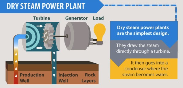
Direct dry steam geothermal power plant is the oldest type of the geothermal power plant which uses the steam taken directly from the geothermal source. Direct dry steam geothermal power plant is the simplest and the most efficient type of geothermal power plant

Parts of direct dry steam geothermal power plant

Geothermal vent

Geothermal vent is a well drilled from the surface of the earth to the geothermal source to extract the steam energy from their up to the turbine of the geothermal power plant.

Steam tank

Steam from the geothermal source is first introduce into the tank where hot water is converted into the steam therefor it is also called steam tank

Separator

After the steam tank there is a separator which removes all the unwanted particles from the steam which could damage the turbine.

Turbine

After the separator steam strike the turbine which convert the pressure energy into the kinetic energy of the generator

Generator

Rotation energy transfer by the turbine to the generator is used by the generator to produce the electricity.

Condenser

Steam after passing through the turbine is transfer to the condenser where it is cooled and then return to the core of the earth.

Working of the direct dry steam geothermal power plant

A deep well is drilled into the earth up to the geothermal source. Super-heated water moves up through the pipes into the tank where water is converted into the steam and that steam is then passes through the separator and moves toward the turbine where high pressure of the steam is converted in to rotation motion of the turbine by the blades of the turbine of Direct dry steam geothermal power plant. Turbine is connected to the generator which converts the rotation motion into the electricity in Direct dry steam geothermal power plant.

Investment Casting (Lost Wax Process)


Investment casting is expandable mold metal casting process which is also known as lost wax process because the pattern is made up of wax and is melted away when it is heated. Wax is recovered and can be used again and again that’s why this process is called investment casting process.


Steps involve in investment casting

Step 1 

First and most unique step is the making of the patter which is of wax. A few number of pattern are attached to the wax sprue


Step 2

Pattern attached to wax sprue is then fully dipped in the refractory material tank so that it is fully covered by the refractory material. It is them drayed to make it rigid


Step 3 

Pattern is now inverted and heated to remove the wax from it. After the removal of the wax patter is now hollow from inside and metal can be poured in it


Step 4

To remove all the contaminants from the mold it is heated at very high temperature and them hot molten metal is poured into it and then kept for a long time for cooling


Step 5

After the metal is cooled refractory material is removed and pattern is removed from the metal sprue


Advantages of investment casting


  • Complex parts can be manufactured
  • High dimensional control
  • Good surface finish
  • Wax is recovered
  • No machining is required
  • Net shape process


Disadvantages of investment casting


  • Take more time than other processes
  • Expansive than other processes


Shell Molding


Shell molding is the expandable mold metal casting process in which mold is a thin shell of sand held together by the binder usually a thermosetting resin. It was invented by the German in about 1940s. Thickness of the shell mold is about 9 mm


Steps involves in Shell molding


Step 1

A metal plate is used to make the pattern. Shape of the patter is like the shape of shell mold you need. Metal plate is heated and they fixed on a container containing the sand and the thermosetting resign.


Step 2

Container is inverted so that the sand and thermosetting resign may came into contact with each other. Heated plate melts the resign and makes a shell of sand around the pattern.


Step 3

In order to remove the extra sand and uncured resign container is reposition again and plate is detached from it


Step 4

Shell made is not properly cured yet so it is heated in a heater for proper curing.


Step 5

After proper curing shell mold is removed from the patter.


Step 6

Same process is preformed to make the other half of the mold and then both halves are attached in a box and supported by the sand. Molten metal is poured.


Step 7

Finish metal product is removed from the shell mold 


Advantages of shell molding


  • Smother surface of the mold, 
  • Ease for the molten metal to flow. 
  • Good dimensional accuracy. 
  • Machining is not required.  
  • Usually no cracks in casting. 
  • Mechanizing for mass production gives good results


Disadvantages of Shell Molding


  • Most expansive metal pattern. 
  • Takes more time.  
  • Not suitable for small production


Kaplan Turbine : Parts, Working, Advantages and Disadvantages

Kaplan turbine is from the reaction turbine categories of hydraulic turbine. Kaplan turbine is name after its inventor Viktor Kaplan. It was the first hydraulic turbine which work in low head and high flow rate. 

Kaplan turbine is also known as the propeller turbine because its blades are just like propeller and working phenomena is same but opposite in direction and this make Kaplan turbine fit for use in rivers and low head area.

Its recommended to read our article on Francis Turbine and Pelton Wheel Turbine to know all about their parts, working and advantages and disadvantages. 

Parts of Kaplan Turbine

Hub

Hub is the part on which blades of the turbine are attached which is attached to the central shaft of the turbine

Blades

Blades of the Kaplan turbine are like the propeller. Blades of other axial turbine are planer but that of Kaplan are not planer instead they are of twist shape along the length to allow the swirling flow of water at entrance and exist.

Guide vanes or wicket gates

Function of the wicket gate is to direct the flowing water toward the blades of the turbine

Shaft

Rotation motion of the blades is transfer to the generator by means of shaft which is a long solid part of the turbine.

Blade control mechanism

Blades at point of their attachment have movable joints. Blade control mechanism control the angle of attack by which water will strike the blades by rotating the blades because of their movable joint.

Governing mechanism

Governing mechanism control the movement of the guide vanes. When power requirement is high it open the guide vane and when power requirement is low is close the guide vanes

Scroll casing

The whole mechanism of the Kaplan turbine is closed in a casing called scroll casing. Scroll casing take water from the resource and direct it towards the blades with the help of the guide vanes.

Draft tube

Waster after passing through the blades is take put of the turbine by the means of the draft tube. Draft tube decrease the velocity of the water by increasing its area.


Kaplan Turbine Parts Diagram

Working of Kaplan Turbine

Water having low head and high flow rate is collected by the scroll casing whose continuously decreasing are in flow direction make shore that water moves with the uniform velocity until it reached the guide vanes and water then directed toward the blades by the guide vanes. 

Between guide vanes and blades their is a curve passage whose main function is to convert the radial flow of water into the axial flow. 

After the curve passage water flow over the blades and creates the high and low pressure region and thus their establish a lift force which force the blades to move from high pressure region to low pressure region.

To learn the difference between different turbine type read our article Frances Turbine vs Kaplan Turbine

Advantages of Kaplan Turbine

  • Runner vanes are adjustable
  • In Kaplan Turbine a very low head is required
  • Kaplan Turbine has very small number of blades 3 to 8
  • Very less resistances have to be over come

Disadvantages of Kaplan Turbine

  • The disposition of shaft is only in vertical direction
  • A very large flow rate is required
  • In Kaplan Turbine a specific speed is 250-850
  • In Kaplan Turbine a heavy duty generator is required