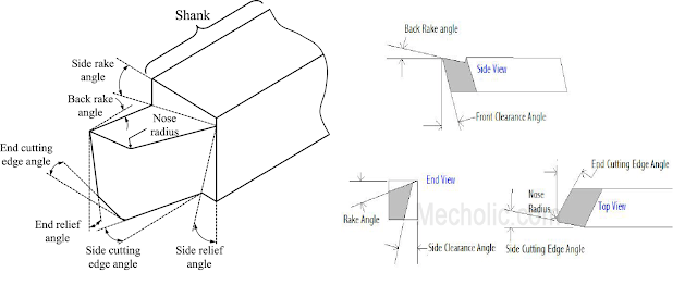
Tool Geometry
Cutting Tool Geometry
1. Shank:
It is the body of the tool. It includes the part of tool which is inserted in tool post to hold the tool in machine. In simple words, it joins the handle and operational end.
2. Flank:
The surface of the tool adjacent to and facing work piece is called flank. A tool have two types of flanks i.e. major and minor flank. Major flank is also called side flank whereas minor flank is also called end flank. Minor flank is the end face of the tool which is facing the work piece while major flank is the adjacent surface to the minor flank.
3. Base:
The opposite side of shank with respect to the top side of tool is known as base.
4. Face:
Rake surface is also called tool face. This allows the chips of work piece to flow over the tool.
5. Cutting edge:
The edge of tool that removes material by coming into contact with work piece is known as cutting edge. A tool have two cutting edges.
i. Side cutting edge: Top edge of side flank is knows as side cutting edge.
ii. End cutting edge: Top edge of end flank is known as end cutting edge.
6. Nose or cutting point:
The point on the tool that separates end cutting edge from side cutting edge is known as nose.
7. Nose radius:
The point where end and side cutting edge meet is given a rounded. The radius given to the intersection point is called nose radius. Nose radius determines the surface quality of the work piece. It also has an effect on tool’s life.
8. Heel:
Intersection of flank and base is called tool heel.
Angles of Single Point Cutting Tool
There are several types of angle in a cutting tool. Each angle have its own importance and function.
1. End Cutting Edge Angle:
It is the angle formed between end face of the tool and plane normal to the side of shank.
2. Side Cutting Edge Angle:
The angle formed between major flank and the longitudinal axis of the tool is known as side cutting edge angle.
3. Back Rake Angle:
The angle made by the face of the tool and plane parallel to the base of tool is known as back rake angle. If the angle is measured in the direction of shank then it is called back rake angle and if it is measured in a direction perpendicular to the shank then it is called side rake angle.
4. End Relief Angle:
It is the angle between side flank and the plane perpendicular to the tool base is known as end relief angle. It prevents the tool from rubbing against the job.
5. Lip Angle/ Wedge Angle:
Angle between the face of tool and end flank is known as lip or wedge angle.
6. Side Rake Angle:
The angle between the face of the tool and plane normal to shank is known as side rake angle.
7. Side Relief Angle:
The angle between portion of side flank immediately below the side cutting edge and line perpendicular to base of tool measured at right angle to side is known as side relief angle. It prevents interference when tool enters the material.
Single Point Cutting Tool Material Properties
Tool can be made of different materials depending upon the material which is being machined. Three important properties of tool material are given below.
• Hardness: Hardness is the property of the material with which it resists to indentation. The strength exhibited by the tool is directly related to the hardness of material with which the tool is made. Hot hardness is the ability of a material to maintain its hardness at high temperature.
• Toughness: Toughness tells us the about the energy which a material absorbs prior to its fracture. It is usually characterized by a combination of strength and ductility in the material. A material with high value of toughness exhibits good resistance against shock load, fracturing and chipping. For a tool, toughness and hardness vary opposite to each other.
• Wear resistance: A material with high hardness show good wear resistance. Moreover, a tool with good surface finish exhibits good wear resistance due to lower coefficient of friction. The property of wear resistance seems simple but most of the people can’t comprehend it properly. Wear resistance decides the life of tool before its replacement.

No comments:
Post a Comment