Finite element analysis of a heat exchanger is done in order to avoid the process of experimentation and improvement on physical products. The finite element analysis on the flat plate heat exchanger for waste heat recovery system will help analyse the performance of flat heat exchanger and make improvement in design or operating parameters to get best result possible.
The finite element analysis done by T. Kho (1999) on a flat plate heat exchanger to understand the flow of fluid on the plate during the operation involves four different shapes of plates. The main focus of T. Kho (1999) was to analyse the effect of parameters like velocity and shape of the flat plate used, on the flow of liquid in flat plate heat exchanger. His work involves plate of different geometry which includes four different profiles as shown below. T. Kho (1999) concluded that during working of flat plate heat exchanger velocity of fluid with which it flow in channels of flat plate heat exchange is the most important factor in deciding the occurring of fouling. The work concluded that low velocity with high temperature cause fouling in flat plate heat exchange and to avoid this redesigning of flat plate heat exchange plate is needed. T. Kho (1999) improves geometry of plates of flat plate heat exchange by placing the distributers at different places of plate. This diverge the flow of fluid which help to avoid fouling in plate heat exchange.

Figure 10
plate with diverters T. Kho (1999)
This
experimental work predict that to make fluid flow more smooth in a flat plate
heat exchange, the adjacent corners of the flat plates should be made circular
rather than with sharp edged. This smooth curve corner will allow more evenly
distribution of fluid flow over the plates. The effect of distributors and the
effect of smooth corner on the flow of the fluid and temperature distribution is
shown below. The figure show that the smoother the corner are smoother will be
the distribution of flow on the plates of flat plate heat exchange and greater
will be the distribution of temperature all over the plate of flat plate heat
exchange.

Figure 11
flow and temperature distribution with diverters
T. Kho (1999)
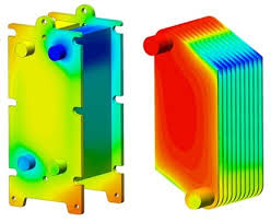
Flavio (2006) work to perform experimental and numerical
investigation of flat plate heat exchanger in order to understand the role of
CFD in predicting the heat transfer in flat plate heat exchanger using a 3 D
model. This work makes use of small flat plate heat exchanger where plate of 90
mm by 60 mm in length and width were used during the experiment and simulation.
Thickness of plate of flat plate heat exchanger was 1 mm and the heat transfer
area available was 0.005 meter square per plate with total of 3 plates used for
this process. Flavio (2006) make use of counter concurrent Z type flow in flat
plate heat exchanger experiment where experiment was conducted in 2D and 3D
model. Results from the analysis shows transfer of temperature from hot fluid to
cold fluid when hot fluid moves between hot fluid channels. The temperature
profile shows decrease in temperature of hot fluid as fluid moves from A and C
plate. It also show how the diagonal corner of the plate of flat plate heat
exchanger has lowest temperature recorded. Similarly the plate B and C of flat
plate heat exchanger shows the increase in temperature of cold fluid this also
show the same phenomena where diagonal corner of the plate of flat plate heat
exchanger has lowest temperature recorded.

Figure 12
Temperature pattern in plate heat exchanger Flavio
(2006)
This difference is temperature value in an individual plate of
flat plate heat exchanger is explained by the fluid flow pattern of flat plate
heat exchanger. As shown in the figure below the flow of hot and cold fluid in
the opposite corners of the inlet is almost zero. If hot and cold fluid does
not reach that point then the heat transfer process in those corners will not
occur. This is the reason that temperature in those regions is very low.
Figure 13
velocity pattern in plate heat exchanger Flavio (2006)
Pressure
drop across the flat plate heat exchanger is mainly due to the resistance face
by the fluid while flowing in the channels of the flat plate heat exchanger. The
resistance faced by the fluid usually dependent on the type of flow, the flow
rate and the geometry of the plate used in the flat plate heat exchanger.
According to the study of the Funke (2019) the literature available on the
pressure drop of the flat plate heat exchanger has very large difference for
different authors and some inaccuracies as well. Funke (2019) work briefly
discusses the pressure drop across the flat plate heat exchanger. It was
concluded in that work that the turbulent flow increases the fluid ability to
transfer heat. This increase in fluid ability to transfer more heat in its
turbulent state is due to the fact that turbulent flow enables fluid mixing
between different layers of the fluid which give better temperature average in
fluid as well as greater fluid areas for heat transfer. This increase heat
transfer due to turbulent flow comes at the cost of higher pressure drop across
the heat exchanger. Higher pressure loses across the heat exchanger means more
work input at the pump is required. The pressure drop across the flat plate
heat exchanger can be calculated as follow (Funke, 2019).
In
above equation delta p represent the pressure drop across the flat plate heat
exchanger, f represent the fanning friction factor or also called the fanning
factor of flat plate heat exchanger channel, omega represent the average
velocity of the fluid inside the channels of flat plate heat exchanger, L
represent the effective length of the flat plate heat exchanger, row represent
the density of the fluid of flat plate heat exchanger and D represent the
equivalent diameter of the flat plate heat exchanger. In above equation the fanning
factor of the flat plate heat exchanger is the main factor which decide the
pressure drop the across the flat plate heat exchanger. If the fanning factor
is measured correctly the pressure drop across the flat plate heat exchanger
can be calculated with the precision of 50 % up to 100 %. The fanning factor of
the flat plate heat exchanger totally depends on the geometry of the flat plate
heat exchanger so the fanning factor calculated for a typical heat exchanger is
only applicable for that flat plate heat exchanger.
As
explained earlier that the mass flow rate and the plate geometry of flat plate
heat exchanger are the two main factor effecting the pressure drop of heat
exchanger and the work of Aydin (2009)
show the effect of plate geometry and mass flow rate of on the pressure drop of
the flat plate heat exchanger. Work
involves the comparison of three different plates of flat plate heat exchanger each
have different geometry in terms of the plate face where fluid will flow. First
type of the plate of flat plate heat exchanger has a flat face for both hot and
cold fluid channel, the second type of plate of flat plate heat exchanger has a
corrugated face and third type of plate of flat plate heat exchanger has an
asterisk face. The face of the corrugated plate of flat plate heat exchanger
shown below is made with the help of die which extrude the material from one
side of the plate face to get corrugated feature and impression on the other
opposite face of the plate. Asterisk face of the third plate of flat plate heat
exchanger is also manufactured in very similar manner where start like shapes
where manufactured using a die to press manufactured the star shape on plate. Plates
used in flat plate heat exchanger by the Aydin (2009) have rectangular cross
section with holes present at each corner of the plate to enable hot fluid and
cold fluid to enter and exit the flat plate heat exchanger.

Figure 14 asterisk and corrugated plate for Heat exhanger Aydin (2009)
The
comparison made by Aydin (2009) show that the energy loss in the corrugated
plate flat plate heat exchanger is much more as compared to that of the
asterisk plate flat plate heat exchanger and the energy loss at asterisk plate
flat plate heat exchanger is much more as compared to that of the flat plate of
flat plate heat exchange. This greater loss of energy at the corrugated plate
flat plate heat exchanger is due to the greater resistance faced by the fluid
during its flow inside channels of corrugated plate flat plate heat exchanger.
Greater the resistance made by the plate of flat plate heat exchanger more
turbulent will be the flow and turbulent flow of the fluid requires greater
force or power to flow. Due to this reason the turbulent flow of the fluid have
greater energy loss as compared to the laminar flow at flat plate of flat plate
heat exchanger. In Aydin (2009) work finds that greater the turbulent flow is
greater is the heat transfer happening inside the flat plate heat exchanger. So
the heat transfer in corrugated plate flat plate heat exchanger is much more as
compared to that of the asterisk plate flat plate heat exchanger and the heat
transfer at asterisk plate flat plate heat exchanger is much more as compared
to that of the flat plate of flat plate heat exchange. Aydin (2009) also worked
to find the effect of mass flow rate on the energy losses, pressure losses and
the heat transfer in flat plate heat exchanger. According to work the increase
in mass flow rate of the hot fluid enables the flat plate heat exchanger to
have better heat transfer from hot fluid to cold fluid whereas the same
increase in mass flow rate also increases the energy loss in flat plate heat
exchanger. This explained by the fact that increases in mass flow rate of the hot
fluid in flat plate heat exchanger increases the turbulent nature of the flow
which enable better heat transfer and greater pressure loss in flat plate heat
exchanger.
Galezzo
(2006) used computational fluid mechanics CFD to solve the flat plate heat
exchanger with the help of ANSYS fluent software. Work starts with the
development of the cad model inside the ANSYS software which was then meshed
and solve for heat and momentum transfer. T.Kho (1992) makes use of computational fluid
mechanics in ANSYS CFX to solve the same heat and momentum transfer equation
for the flat plate heat exchanger. Work pattern of T.Kho (1992) was very
similar to that of the Galezzo (2006) where work started with the computer
added model, meshing and then finally the solution of the flat plate heat
exchanger.
No comments:
Post a Comment