Heat exchanger is a simple device used to transfer
heat from source of high potential (hot fluid) to the sink of low potential
(cold fluid) separated by the metal body. The exchange of heat from the high
potential to low potential is done using the laws of thermodynamics and theory
of heat and mass transfer (Irfan
2013).
The exchange of heat between fluids happened without the transfer of mass so
the system of the heat exchanger is a close system where only heat and energy
is transfer between systems and no mass is transfer between systems. Working of
a heat exchanger is very simple as it completes in three simple steps (T.D Eastop, 1993). The first step is when metal
which separate the hot fluid from cold fluid absorb the heat from hot fluid
during its contact with hot fluid. Second step is when heat from one side of
metal plate is transferred to other side of the metal plate. Third step is when
heat from cold fluid side of the plate is transferred to the cold fluid during
its contact with hot fluid.
Figure
1 U tube heat exchanger for waste heat recovery
(T.D Eastop, 1993)
Conduction
Conduction is a phenomena of heat
transfer where heat transfer using a solid medium like metal and any other
material. As conduction is medium dependent so the parameters of medium like
material, temperature and surface area will control the process of heat
transfer (Irfan
2013).
If heat transfer is represented by Q, conductive heat transfer coefficient by
k, area by A and temperature difference by delta T then conduction can be
calculated as follow (T.D
Eastop, 1993)
Q=k*A*∆T
Convection
Convection is a phenomenon of heat
transfer where heat transfer using a fluid medium like water or air. As
convection is medium dependent so the parameters of medium like type of fluid,
temperature and surface area will control the process of heat transfer (Irfan 2013). If heat transfer is represented
by Q, convective heat transfer coefficient by h, area by A and temperature
difference by delta T then convection can be calculated as follow (T.D Eastop, 1993)
Q=h*A*∆T
Waste Heat Recovery
Industrial unit which involve huge amount of heat is any of their process usually waste a good amount of it to their surrounding due to certain limitations and product requirements. A good use of that waste heat energy is to utilise that heat in the heating of raw material or as a fuel for any other process. System developed for this type of applications is called the waste heat recovery systems and they are design for a sole purpose of utilizing the heat energy as a fuel for heating the fluid (Irfan 2013). In almost every case of waste heat recovery system the heat exchanger made the most of the system. In waste heat recovery system heat exchanger absorb heat from one fluid which is the waste of any industrial process and transfer it to the second fluid which further used any good work. Heat exchanger developed for this purpose should have high efficiency and excellent performance as it will be only source of energy in the system (T.D Eastop, 1993).
Shell and Tube Heat Exchanger
Shell and tube heat exchanger is a
type of heat exchanger which makes use of shell surrounding the more than one
tube for the transfer of heat from hot fluid to cold fluid. In regular setup
the tubes contain cold fluid and shell contain hot fluid (Durges 2014). This gives greater surface area
to the cold fluid to absorb heat from hot fluid as each tube of U tube heat
exchanger containing the cold fluid is surrounded by the hot fluid. This type
has a straight tube which runs from the inlet of hot fluid to the entire length
of the heat exchanger up to the outlet of the shell and tube heat exchanger (Asawari, 2016).

Figure 3 shell and tube heat exchanger (Asawari, 2016)
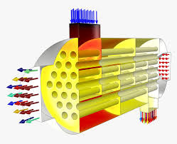
U tube Heat Exchanger
U tube heat exchanger is a type of
shell and tube heat exchanger which make use of shell surrounding the more than
one tube which also bends at 180 degree inside the shell for the transfer of
heat between hot fluid and cold fluid. In regular setup the tubes contain cold
fluid and shell contain hot fluid. This gives greater surface area to the cold
fluid to absorb heat from hot fluid as each tube of U tube heat exchanger
containing the cold fluid is surrounded by the hot fluid (Durges 2014). This type of heat exchanger has
straight tubes which run from the inlet of hot fluid to the entire length of
the shell of heat exchanger up to the outlet of the shell and tube heat
exchanger. U tube heat exchanger contains more length of tube as compared to
straight tube type which enables greater heat transfer within the same length
of shell (Asawari,
2016).

Figure 4 u tube heat exchanger(Asawari, 2016)
Tube Material Selection
Tube
of U tube heat exchanger contains cold fluid inside it and its function is to
hold the cold fluid inside it at high pressure and increasing temperature.
Other than this the tube provides the channel for the flow of cold fluid to
enter and leave the U tube heat exchanger. The material requirements for tube
of u tube heat exchanger is those mechanical and thermal properties which
enable tube to hold fluid at high temperature and pressure and at the same time
make it light weight and cost effective. Based on the working principal and
operation involve in life of tube of U tube heat exchanger the mechanical and
thermal properties required by a material are high thermal conductivity, high
strength, corrosion resistance, low density, low thermal expansion, wear
resistance, high machinability, good weldability and low cost (Rajesh Ghosh
2013). Copper and aluminium are the materials which are mostly used for the
tubes of u tube heat exchanger as they have high thermal conductivity from all
the material recommended for the u tube heat exchanger. Copper and aluminium
also have highest tensile strength but also have high thermal expansion. Both copper
and aluminium are corrosion free and has excellent machinability and
weldability. The density of both copper and aluminium are low which make tube
light weight and but the cost of material is high as compared to other
materials.
No comments:
Post a Comment