Aug 17, 2020

5 Eco Friendly Heat Energy Resources for Organic Rankine Cycle

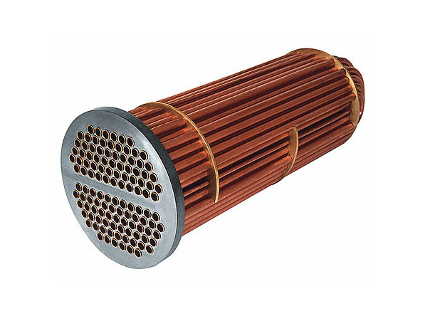
Organic Rankine cycle ORC is one of the best options available for small scale efficient energy production systems. In Organic Rankine Cycle an organic fluid is used in the Rankine cycle instead of water as the organic fluid has a lower boiling point as compared to water so required less heat input. Waste heat from any source, when combined with organic Rankine cycle ORC using a heat exchanger like shell and tube heat exchanger, make it the best and most environmentally friendly energy solution. Optimize parameters allows the minimum mass flow rate and less area required for the heat exchanger saving power and cost required at the heat exchanger system without compromising the efficiency of the system. 
Save Environment And Green Power Concept. Stock Vector ...

With a continuous increase in the world population, the problems associated with human needs are also increasing. One such problem is the need for energy to meet certain needs like electricity. In today’s industrial world where there is a complete working industry for every human need, every industry itself has a need and the biggest of them is electricity.  The world current setup to meet its need for electricity heavily depends on the use of natural resources which has increased to its maximum in the present time (Energy.gov, 2019). Natural resources like coal, gas, and fossil fuel on which humanity depends to meet their need for electricity have limited known stock due to which researchers and engineers are forces to developed new resources to produce electricity(Energy matter 2019). The use of natural resources like coal is also harmful to the earth's environment and the current use of this type of natural resource to produce electricity has polluted every land, river, sea, and even oceans. So there is a desire need to develop some renewable and alternative resources which can produce clean electricity. 

Figure 1 global energy consumption [(energy.matter, 2019).

 
Figure 2 energy consumption by resources (energy.gov, 2019).

There are some methods already developed like solar farms, wind turbine farms, geothermal sources, and hydroelectricity which use renewable natural resources like sunlight, wind, geothermal heat sources, and flowing water for electricity production (Energy matter 2019). All these resources do not harm the environment as coal or natural gas do and they all are also renewable but these resources have limitations of their now. The hydroelectric method is only possible in those locations that the huge amount of flowing water with the all necessary setup to store and control the flowing water. Solar farms need continuous sunlight for production which limits their use to an area with getting sunlight 12 months a year but still they only operate during the day timing. The wind farm covers a lot of surface area and they are also limited to geographic regions that have potential wind energy 12 months a year.

Contrary to this the conventional resources do not have regional limitations and product electricity 24/7 for 365 days a year but they pollute the environment and with limited natural resources world cannot rely on them for long. So there is a need to integrate conventional resources with renewable ones to increase electricity production without affecting the environment. One such way is to run steam power plants with renewable resources as one of the most commonly used and high energy production methods having quite good overall efficiency as compared to other methods of electricity production. Steam turbines operate on the Rankine cycle uses conventional methods to heat water and produce steam at the required temperature and pressure. An improved form of regular Rankine cycle is the Organic Rankine Cycle which uses an organic fluid in the place steam as its main working fluid. This research work optimizing the organic Rankine cycle with the help of renewable and alternative resources.

Hybrid Organic Rankine Cycle
In the hybrid organic Rankine cycle, a renewable and alternative source of heat is used in the place of a conventional boiler and fuel-burning systems. In one of the systems, a solar heater is used to heat the organic fluid and convert it into steam during the day time and biofuel is used to heat organic fluid at night. The solar heater collects solar heat at its collector and transfers it to a fluid that fluid carries that heat to an organic fluid of the Rankine cycle and heat the fluid until it converted into steam. Conversion of heat happens in a heat exchanger which also works as a biofuel burner during the night time to heat the organic fluid (S. Quoilin 2011).
 
Figure 3 Hybrid Rankine Cycle (S. Quoilin 2011)

Heat Source for Hybrid ORC
A conventional organic Rankine cycle makes use of conventional resources for the heat they required to vaporize the organic fluid inside the boiler stage of the Rankine cycle. The conventional resource of heating in the organic Rankine cycle is the burning of fossil fuel. To transfer the dependence from fossil fuel, the use of alternative and renewable fuel is needed for the organic Rankine cycle. 
There are a number of alternative resources available for the heating of organic fluid of organic Rankine cycle and they are explained as follows.

1. Waste Heat Recovery
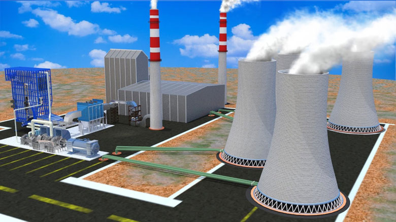
One of the best, biggest, and most efficient sources of the heat for the organic Rankine cycle is the waste heat coming out of any heating source. This source of heat or organic Rankine cycle is considered best as it does not require any running cost of the organic Rankine cycle. The waste heating coming out of any industrial unit or domestic unit can be used as a heat source for the organic Rankine cycle and the fact that organic fluid of organic Rankine cycle needless amount of heat as compared to water for vaporization makes this waste heat source quite effective for organic Rankine cycle. Using waste heat recovery for the organic Rankine cycle also requires less initial investment as only a heat exchanger is required for extracting waste heat and transferring it to the organic fluid of the organic Rankine cycle.

2. Biomass 
Biomass as a heat source for the organic Rankine cycle is one of the simplest, cost-effective, and environmentally friendly sources. This limitation of biomass as a fuel is the low quantity of temperature obtains from it does not apply here as the organic fluid of the organic Rankine cycle requires less temperature or heat to get vaporize as compared to water. The biomass as a source of heating does not require the high cost of running the organic Rankine cycle as biomass is usually a waste product of a process that will decompose in nature if not utilized. Some of the advantages of utilizing the biomass as fuel in organic Rankine cycle are, it does not require any specific or expensive machine or set for heating, it is not restricted to any specific area or conditions, it does not have high operation cost and it is completely environment friendly. 

3. Geothermal
The geothermal source of heat for the organic Rankine cycle is considered effective and efficient as it clean, alternative, and renewable source of the heat of the organic Rankine cycle. This source of heat does not require any boiler cost of machinery but the setup required for the geothermal source of heat involves high initial cost. Geothermal source of heat in the organic Rankine cycle does not have high operation costs but has a high limit of the geographic location of the geothermal source. Geothermal source of heat in the organic Rankine cycle is very economical and is highly environment friendly.

4. Solar Heating
Using heat available in the sunlight to heat the organic fluid of the organic Rankine cycle is also an effective, efficient, renewable, and cost-effective solution. This alternative and renewable resource of heating require only a single solar collector which can focus sun rays onto a pipe containing specific fluid usually a refrigerant. The solar heating methods also required a heat exchanger to transfer solar heat absorbed by the refrigerant to the organic fluid of the organic Rankine cycle. This method of heating in the organic Rankine cycle does not require any fuel to operate, does not have a hard geographic limitation, and is super environment friendly but is only applicable during the day timing. Due to this limitation, an extra source of heat is always required in this method which also increases its cost of installation and operation.

The different energy sources which can be used to provide the heat required for the organic Rankine cycle include waste heat energy from industrial units, solar heat energy, geothermal energy, and biomass. From these available energy resources, the waste heat from the industrial unit is most favorable as it does not require any running cost of the organic Rankine cycle. Using waste heat recovery for the organic Rankine cycle also requires less initial investment as only a heat exchanger is required for extracting waste heat and transferring it to the organic fluid of the organic Rankine cycle. For this study waste heat coming out of the kiln of the cement factory where a lot of heat is wasted into the environment as the end of the process will be used. The fluid which contains heat moving out of the kiln and into the environment is simple heated air. Shell and tube heat exchanger with the optimum design parameters of the organic Rankine cycle was designed in such a method its required minimum mass flow rate of air which allows energy saving at the pump and cost-saving at the heat exchanger installation and maintenance without compromising the efficiency of the system. 

Aug 10, 2020

Rankine Cycle of Steam Power Plant

Steam turbine power plant follows the Rankine cycle during one complete cycle of steam though different component of power plant for electricity production. Steam turbine power plant consists of five main components boiler, turbine, recuperator, condenser and pump (Yamamoto, 2001). Work starts from the boiler which heats the water to make steam at required temperature and pressure. Steam is then used by the steam turbine to rotate generator attached to it. Steam then passes though condenser which convert steam into water again. Some of steam is directed into condenser through recuperator to heat up the water coming from condenser. This increases the efficiency of the system. Pump is placed between condenser and recuperator to provide the require flow rate to the water (Yamamoto, 2001). 
Increase Efficiency of Steam Power Plants - Industry Today

Ranking Cycle Working
Pump
Pump of power plant has only one function and that is to provide the fluid with the required pressure and low rate so that the fluid can circulate the entire power plant without any issue. The work input of the pump is very small as compared to the all other components work input or work output. 

Boiler
Boiler of the power plant is the main work input component of the power plant which makes use of the heat provided by the burning of the fossil fuel to heat the fluid present inside the boiler. Heating the fluid converts the liquid into high temperature and high pressure vapor. This high temperature and high pressure fluid will do work in turbine stage.

Turbine
Turbine of the power plant perform two task, one is the absorbing the energy of the high temperature and high pressure fluid to rotate itself and second the use its rotation to generate electricity through generator. In this stage work in done by the fluid onto the turbine blades so the this stage is considered as the work output stage of the power plant
File:Rankine cycle layout PL w gen.png - Wikimedia Commons
Condenser
Condenser of the power plant is heat rejection unit of the power plant which removes the unnecessary heat from the fluid. Condenser is cooling tower or a heat exchanger which absorbs heat from fluid and converts the vapor into liquid state. Liquid coming out of the condenser enters the pump to complete the circuit of the power plant. 

Thermodynamic Working of Rankine Cycle
Isobaric Heat Transfer 
As the Rankine cycle starts from the pump of power plant the heat or energy input by the pump is considered as the isobaric heat transfer in to the fluid and it is presented as point 1 to 2 in T-S graph and P-H graph of Rankine cycle (Yamamoto, 2001). Similarly in boiler of the power plant the heat in provided to the fluid until it converted into the high temperature high pressure steam and this process of heat transfer is also isobaric heat transfer. Boiler of power plant is present as the point 2 to 3 in T-S graph and P-H graph of the Rankine cycle. 

Isentropic Expansion
The next stage of the Rankine cycle is the turbine stage which receives high temperature high pressure fluid in vapor state. Vapor enters the turbine where they expand in turbine by rotating the blades of the turbine. This process reduces both temperature and pressure of the vapors thus making the process of expansion as isentropic expansion. This process of isentropic expansion is presented as 3 to 4 in T-S graph and P-H graph of Rankine cycle. At the end of the turbine stage the fluid exit in two states that is in liquid and vapor state, this is due to the reason that the reduction in temperature and pressure convert some of vapor into liquid while other remain in the state of vapor (Yamamoto, 2001).


Isobaric Heat Rejection 
Vapor and liquid coming out of turbine has still very high enthalpy and entropy due to which is needed to be condensed into liquid state by lowering the enthalpy and entropy of the fluid. The process of removing the heat without lowering the temperature and pressure of the vapor is called the isobaric heat rejection. This process of isobaric heat rejection is presented as 4 to 5 in T-S graph and P-H graph. The fluid should be in liquid state before it enters the pump and boiler of the power plant and due to which the condenser should remove enough heat from fluid to convert vapor into liquid.

Isentropic Compression
As vapor is converted into the liquid state by the condenser the flow rate of the fluid decrease and pressure required at the boiler feed is also higher as compared to the pressure of the fluid after condenser. The role of the pump is to provide fluid the required flow rate and pressure and the process of increase in pressure and flow rate is the isentropic compression process where temperature and pressure of the fluid increase a little but enthalpy and entropy remain constant. 

Rankine Cycle Calculation
The major calculations involve in the power plant controlling Rankine Cycle are about the work and heat added by the pump and boiler of the power plant respectively, work done by the turbine of power plant and heat rejected by the condenser of the power plant. 

Heat Addition in Rankine Cycle
Work and heat added in fluid of the power plant controlled by the Rankine cycle is done by the pump and boiler of the power plant respectively. Work added by the pump is very small as compared to the boiler of power plant but still the heat added by the pump of a large power plant is considerably high. 

Heat added by pump
Work added by pump in fluid of Rankine cycle is the calculated by the change in enthalpy of the fluid coming into the pump and going out of the pump. It can be calculated as follow
                                        W pump=Hout-Hin
As enthalpy before the pump stage is presented as H5 in the P-h graph and enthalpy out of the pump is presented as the H1 in the P-h graph so
                                         W pump=H1-H5

Heat Added by Boiler
Heat added by boiler in fluid of Rankine cycle is the calculated by the change in enthalpy of the fluid coming into the boiler and going out of the boiler. It can be calculated as follow
                                        Q boiler=m(Hout-Hin)
As enthalpy before the boiler stage is presented as H1 in the P-h graph and enthalpy out of the pump is presented as the H3 in the P-h graph so
                                        Q boiler=m(H3-H1)

Work Done in Rankine Cycle
Work done by fluid and heat rejected by the fluid of the power plant controlled by the Rankine cycle is done by the turbine and condenser of the power plant. Work done by the fluid on the turbine is much more as compared heat rejected by the condenser of the power plant.

Work done on Turbine
Work done by fluid on turbine of Rankine cycle is the calculated by the change in enthalpy of the fluid coming into the turbine and going out of the turbine. It can be calculated as follow
                                    W turbine=m(Hout-Hin)
As enthalpy before the turbine stage is presented as H3 in the P-h graph and enthalpy out of the turbine is presented as the H4 in the P-h graph so
                                    W turbine=m(H3-H4)

Heat Rejected by Condenser
Heat rejected by condenser in fluid of Rankine cycle is the calculated by the change in enthalpy of the fluid coming into the condenser and going out of the condenser. It can be calculated as follow
                                    Q condenser=m(Hout-Hin)
As enthalpy before the condenser stage is presented as H4 in the P-h graph and enthalpy out of the condenser is presented as the H5 in the P-h graph so
                                    Q condenser=m(H4-H5)

Energy Balance of Rankine Cycle
For an ideal case the heat and work provided to the fluid by the boiler and pump of the Rankine cycle is utilized fully in the turbine and condenser of the Rankine cycle in the form of work and heat respectively. Due to the complete consumption of heat and work done onto the system the equation of energy balance of an Ideal Rankine Cycle can be written as follow
                           (Q boiler-Q condenser)-(W turbine-W pump)=0

Thermal Efficiency of Rankine Cycle
Ability of the turbine of the Rankine Cycle to convert the heat provided to the fluid by the boiler into useful work is called the efficiency of the Rankine Cycle. It can be calculated as follow
                        efficiency=1-(q condenser)/(q boiler)
In the above formula the heat removed or the heat involve in the condenser is used. The heat present in fluid before it enters the condenser stage is the heat left after the turbine stage. Heat consumed by the turbine is considered in this manner.

Thermal Efficiency of Steam Turbine
Thermal efficiency of the steam turbine can be calculated as the work done by the turbine divided by the input provided by the boiler. The turbine work can be calculated as the heat removed or the decrease in enthalpy of the steam after the turbine stage and boiler input can be calculated as the increase in enthalpy after the boiler stage.
                            Turbine efficiency=(W turbine)/(Q boiler)
                            Turbine efficiency=(H3-H4)/(H3-H1)

Carnot Efficiency
Carnot efficiency is the maximum theoretical efficiency which a heat engine can have while converting high temperature into work. If a heat engine work between a high temperature source and low temperature reservoir then the efficiency of the Carnot engine can be written as  
                            Carnot efficiency=Work/( Input)*100
                            Carnot efficiency=(Thot-Tcold)/Thot*100
                            Carnot efficiency=1-Tcold/Thot*100

Pump Efficiency
The efficiency of the pump is predefined by the manufacturer in most of and it depends on the density of the fluid to move, flow rate at which fluid will move, heat which pump can attain and the power input given to the pump.
                    pump efficiency=(ρ*g*Q*H)/(Power or Work input)

Aug 3, 2020

Designing a U tube Heat Exchanger for Waster Heat Recovery

Heat absorb by cold fluid of U tube heat Exchanger
In U tube heat exchanger the cold fluid usually moves inside the tubes of the U tube heat exchanger whereas the hot fluid surrounds the cold fluid inside the U tube heat exchanger (Asawari, 2016). This gives greater surface area to the cold fluid to absorb heat from hot fluid as each tube of U tube heat exchanger containing the cold fluid is surrounded by the hot fluid. The heat transfer to the cold fluid can be calculated in different methods, one is to due heat exchanger design parameters to calculated the heat transfer and temperature output of the cold fluid coming out of U tube heat exchanger and second is to use fluid working parameters in U tube heat exchanger to calculate the heat transfer to the fluid (Durges 2014). A second method is used here as U tube heat exchanger dimensions are not known at this stage. The heat transfer in Watt to the cold fluid of U tube heat exchanger can be calculated using the cold fluid mass flow rate inside U tube heat exchanger, specific heat of cold fluid and the inlet and outlet temperature of the cold fluid. Complete equation to calculate heat transfer to cold fluid in U tube heat exchanger is shown below (T.D Eastop, 1993)
Q= m_c*  C_pc*( T_co-  T_ci )
Q is the heat transfer in Watt
m_c is cold fluid mass flow rate in Kg/sec
C_pc is cold fluid specific heat in J/Kg.K
T_co is cold fluid outlet temperature in degree centigrade
T_ci   is the cold fluid inlet temperature in degree centigrade
U-Tube Heat Exchangers
Heat Rejected by hot fluid U tube heat Exchanger
In U tube heat exchanger the hot fluid moves in the shell of U tube heat exchanger and it surrounds the tubes of U tube heat exchanger (Asawari, 2016). This layout helps better transfer of heat from hot fluid to cold fluid in U tube heat exchanger. The hot fluid will enter the U tube heat exchanger at high temperature and leave the heat exchanger at lower temperature and heat will be transfer from the hot fluid. The methods of calculating the heat lost by the hot fluid is very much same as that of the heat absorb by the cold fluid (Durges 2014). This is case the final temperature is lower as compared to initial temperature due to which during calculation the final temperature will be subtracted from initial temperature to get the positive temperature difference. Other parameter which includes mass flow rate of hot fluid and specific heat of hot fluid have their own specific values for hot fluid moving in shell of U tube heat exchanger (T.D Eastop, 1993).
Q= m_h*  C_ph*( T_hi-  T_ho )
Q is the heat transfer in Watt
m_h is hot fluid mass flow rate in kg/sec
C_ph is hot fluid specific heat in J/kg.K
T_ho is hot fluid outlet temperature in degree centigrade
T_hi   is the hot fluid inlet temperature in degree centigrade

Heat Lost in U Tube Heat Exchanger
According to the laws of thermodynamics it is not possible for a system to transfer all its heat to work and energy (Asawari, 2016). Some of the heat present in the system will be lost to environment, friction and any other losses present in system. Similar to that the heat exchange happening in U tube heat exchanger will not be an ideal case where all heat rejected by hot fluid will be absorb by the cold fluid. Some of the energy will lose to the environment (Durges 2014). Loss of heat can be from the shell of the U tube heat exchanger where heat of hot fluid is absorb by shell material and then transfer to the surrounding environment.  Similar to this some of the heat will be lost with the hot fluid going out of the U tube heat exchanger due to irregular flow of hot or cold fluid inside U tube heat exchanger (T.D Eastop, 1993).
For an ideal case
Q_(tansfer )= Q_(rejected )= Q_absorb
For practical case
Q_(tansfer )= Q_absorb<Q_(rejected )
It also can be said
Q_(rejected )=Q_absorb+Q_lost  

Heat Transfer from hot to cold fluid of U tube heat Exchanger
In U tube heat exchanger the ability of the heat exchanger to transfer heat between hot fluid and cold fluid depends on the design parameters of the U tube heat exchanger (Asawari, 2016). The heat transfer by the U tube heat exchanger depends on the heat transfer coefficient of the U tube heat exchanger, Area of the U tube heat exchanger available for the exchanger of the heat and temperature difference between the input and output of the U tube heat exchanger called the log mean temperature difference of the U tube heat exchanger (Durges 2014).  The below mention equation of the heat transfer in U tube heat exchanger design parameter dependent and can be utilised to determine the design parameters like required area of the U tube heat exchanger.
Q= U*n*A* ∆T_lmtd
Q is heat transfer in Watt
U is over all heat transfer coefficient in W/m^2 K
A is tube area of heat exchanger in m^2
∆T_lmtd is long mean temperature difference in degree centigrade
n Number of tubes

Area of Tube of U tube heat Exchanger
Based on the value of area obtained from the above equation of the heat transfer by the U tube heat exchanger, the value of the area required by U tube heat exchanger to transfer the heat can be calculated (Durges 2014). Utilizing the value of area of U tube heat exchanger required for heat transfer and the standard dimensions of U tube heat exchanger the number of tubes required to have the necessary area of U tube heat exchanger can be calculated (Asawari, 2016). 
A = π*n* d* l
A is area of tube in square meter m^2
d is diameter of tube in meter m
l is the length of the tube from inlet to outlet in meter m
n is the number of tubes

Log mean temperature Difference of U tube heat Exchanger
A single U tube heat exchanger is dealing with two different types of fluids which are entering and leaving the U tube heat exchanger at very different temperatures (Singh 2013). In real life application the heat rejected and absorb by the hot and cold fluid respectively will be different so temperature difference of none of the fluid can be used in the calculation of U tube heat exchanger design parameters calculation. So the temperature difference which considers both fluid temperatures called the log mean temperature difference can be utilised. Log mean temperature difference can be calculated using following formula.
∆T_lmtd=( ∆T_(2 )- ∆T_1)/ln⁡((∆T_2)/(∆T_1 )) 
∆T_lmtd is log mean temperature difference
∆T_(2 ) is temperature difference at outlet
∆T_1 is temperature difference at inlet

Overall heat transfer coefficient of U tube heat Exchanger
In a U tube heat exchanger the heat transfer from the hot fluid to the cold fluid happens through a medium of metal pipe where heat first transfer from hot fluid to the outer surface of the tube using the mechanism of heat transfer called convection heat transfer (Rajesh Ghosh 2013). After this the heat transfer from outer tube surface to inner tube surface using the mechanism of heat transfer called conductive heat transfer (Singh 2013). In last heat first transfer from tube inner surface to cold fluid using the mechanism of heat transfer called convection heat transfer. The transfer of heat using convection, conduction and convection depends on the heat transfer coefficient of convection, conduction and convection. The first convective heat transfer coefficient depends on the hot fluid and tube material relation and thermal properties. The conductive heat transfer coefficient depends on tube thickness and tube material thermal conductivity. The second convective heat transfer coefficient depends on the cold fluid and tube material relation and thermal properties. In design of U tube heat exchanger all three different heat transfer coefficient needed to be considered. An overall heat transfer coefficient of U tube heat exchanger can be calculated using the below mention formula.
1/U=1/(h (tube fluid))+x/(k (tube))+1/(h (shell fluid))
Where
U is overall heat transfer coefficient W/m^2 K
H is convective heat transfer coefficient W/m^2 K
K is conductive heat transfer coefficient W/mK

Pressure Drop in U tube heat Exchanger
The tube side pressure drop is the sum of the pressure drop through the tubes, the pressure drop through the channels and pressure drop through the 180 degree bend,
∆P_T=(f*〖m_h〗^2*l*n)/(2*ρ*g*di)+(4*n〖*v〗^2)/(2*ρ*g)+(k*ρ*u^2)/2
f is constant
mh is tube mass flow rate
l is length of tube
n is number of tubes
ρ is density of tube fluid
g is gravity
di is tube internal diameter

Tube Pitch of U tube heat Exchanger
As more than one tube is required in U tube heat exchanger so the distance at which they can be installed in the U tube heat exchanger should be perfect and calculated so that proper heat transfer can be take place (Rajesh Ghosh 2013). There are two different patterns in which tubes can be placed inside the shell of U tube heat exchanger (Singh 2013). One is the square arrangement where tubes are place in such a manner that they made square cross section at their inlet and outlet. Second is the triangular arrangement where tubes are place in such a manner that they made triangular cross section at their inlet and outlet (Singh 2013). The pitch of the tube basically depends on the outer diameter of the tubes and can be calculated as follow.
Pt=1.25*Tube outer diameter