Effect of Compressive Axial Load on Deflection of the Beam Lab Report
Aim
To determine the effect of compressive axial load due to transverse load on deflection of the beamObjection
1. Experimentally determine the deflection in beam with vertical end2. Experimentally determine the deflection in beam with oblique end
3. Theoretically determine the deflection in beam with vertical end
4. Theoretically determine the deflection in beam with oblique end
Introduction
Beam
A structural member who is designed to resist the bending stresses produce in it when an external load is applied on it.
Simply supported beam
Types of beam which has support available at its both ends is called simply support beam
Overhanging beam
Types of beam which has support available at its both ends but has some of its area extended over one of its ends is called overhanging beam
Cantilever beam
Type of beam which has support available only at one of its ends and other ends is free is called cantilever beam
I beam
Type of beam which has cross section shape like English alpha bet I is called I beam
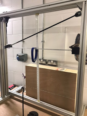
Procedure
Vertical end condition
1. first step in this experiment is to fix the vertical end of the apparatus with the beam
2. After that check the apparatus for any damages or errors present in it. if there is any of them make sure they are removed before experiment starts
3. Third step is attached hanger to the beam at its central point. This is important to attach the hanger in the middle as the apparatus has deflection measuring arrangement only at that point
4. After that add weight of 5 N and check the reading of the beam deflection
5. Repeat the above step for different weight by adding 10 N each time and check the deflection reading for each of them
6. When loaded up to 100 N, start removing weight and check deflection for that point too.
Oblique end condition
1. first step in this experiment is to fix the oblique end of the apparatus with opposite end of the beam
2. After that check the apparatus for any damages or errors produce due to the vertical end condition test. if there is any of them make sure they are removed before oblique end condition experiment starts
3. Third step is attached hanger to the beam at its central point. This is important to attach the hanger in the same spot as done for the vertical end condition test in order to ckect the true effect of oblique end condition
4. After that add weight of 5 N and check the reading of the beam deflection
5. Repeat the above step for different weight by adding 10 N each time and check the deflection reading for each of them.
6. When loaded up to 100 N, start removing weight and check deflection for that point too.
Readings
Force on beam
|
Loaded deflection mm oblique
|
Unloaded deflection mm oblique
|
Loaded deflection mm vertical
|
Unloaded deflection mm vertical
|
Average deflection oblique
|
Average deflection mm vertical
|
5
|
1
|
1.5
|
0
|
1
|
1.25
|
0.5
|
15
|
4
|
3.5
|
3
|
4
|
3.75
|
3.5
|
25
|
6
|
5.5
|
5
|
5
|
5.75
|
5
|
35
|
8
|
7.5
|
7
|
7
|
7.75
|
7
|
45
|
11
|
10
|
10
|
10
|
10.5
|
10
|
55
|
13
|
12.5
|
12
|
12
|
12.75
|
12
|
65
|
16
|
15
|
14
|
15
|
15.5
|
14.5
|
75
|
18
|
17
|
17
|
17
|
17.5
|
17
|
85
|
21
|
20.5
|
20
|
20
|
20.75
|
20
|
95
|
23.5
|
23.5
|
23
|
23
|
23.5
|
23
|
105
|
27
|
26
|
26
|
26
|
26.5
|
26
|
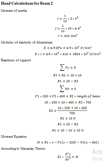
Calculation
Support Reactions
sum of forces in x direction is equa to zero
A-F+B=0
A=F-B
sum of moment is equal to zero
A*0.8=F*0.4
B=(15*0.4)/0.8=7.5 N
A=F-B
A=15-7.5=7.5 N
Shear force
Shear force Before B
Shear force = A=7.5 N
Shear force After b
SShear force = A– F=7.5-15= -7.5 N
Bending moment
At A
Bending Moment = A*L =7.5*0 = 0 Nm
At B
Bending Moment = F*L =1 5*0.4 =6 Nm
At C
Bending Moment = B*L =75*0 = 0 Nm
Beam Deflection
moment of inertia=1/12 a*b^3
moment of inertia=1/12*50*〖125〗^3
moment of inertia=8*〖10〗^(-9) m^4
modulus of elasticity=-(Force*〖Length〗^3)/(48*deflection*moment of inertia)
modulus of elasticity=-(15*〖0.8〗^3)/(48*0.003*8*〖10〗^(-9) )=6666666667 Pa=6.67 GPa
The actual value of modulus of elasticity for aluminium is 68 GPa which is far too much as compared to the experimental value of modulus of elasticity of aluminium which is only 6.67 GPa. The difference between values of modulus of elasticity is may be due to faults in apparatus or due to the errors made by operator during experimentation and observation.

Compressive force
Compressive load when load is 5 N
C S =(Moment*b/2)/(moment of inertia)
C S =(6*0.0125/2)/(8*〖10〗^(-9) )=4687500 Pa
C S=Force/Area
4687500=Force/(5*125)
F=2929.68N
Moment equation
M=nornmal load bending+axial compressive load bending
Moment=F*L/2+Fc*deflection
M/EI=(〖 d〗^2 y)/(dx^2 )
EI (〖 d〗^2 y)/(dx^2 ) =F*L+Fc*deflection
Integrating
dy/dx =1/EI(F*L^2/2+Fc*deflection*L+C_1
Integrating
y =1/EI(F*L^3/6+Fc*deflection*L^2/2+C_1*L+C_2
Put x=0 y= 0
C_2=0
Put x = 0.4 y = 0
0=15*〖0.4〗^3/6+〖0.4*C〗_1
C1 =0.4
Deflection at 0.4 meter due to load of 15 N
70*〖10〗^9*8*〖10〗^(-9)*y =15*〖0.4〗^3/6+0.14*0.4+2929*y 〖0.4〗^2/2
560y-234y =0.216
y =0.216/326
y=6.63*〖10〗^(-4) m
y =0.66 mm

Discussion
The graph of
deflection made against load is shown below and according to that graph the
deflection of oblique end condition is much more than that of vertical end
condition. According to graph the initial loading which is from 0 to 15 N does
not show much difference in deflection but as the graph moves from 15 to 100 N
load the deflection of oblique end condition increase much more rapidly than
that of the vertical end condition. So from this it can be concluded that the
axial compressive load due to oblique end condition has considerable effect on
deflection of beam.


Comments
Post a Comment